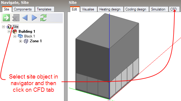
To create a new external CFD analysis, first make sure that you have selected the site object in the model navigator and then click on the CFD screen tab:
The New CFD Analysis dialog is displayed which allows you to name the analysis, define grid generation variables, wind data and the extents of the domain to be included in the analysis:

With External CFD analyses you can select from 2 grid types:
Tip: Uniform grids are preferred for large and or very complex external CFD analyses to encourage convergence.
On entry to the CFD screen after completing and closing the new CFD analysis dialog, the CFD grid is automatically generated throughout the overall external domain extents. The grid is created by first determining key points obtained from constituent model blocks along the major axes, the distance between each of these key points being known as regions. Each CFD grid region along each major axis is automatically spaced using the ‘default grid spacing’ dimension.
A potential problem when generating the grid is the creation of cells with a high aspect ratio that can lead to instability in the equation solver. In order to avoid such cells, grid lines that are very close together can be merged. The grid line merge tolerance is the maximum dimension that will be used in determining whether or not to automatically merge grid lines.
Enter the required free stream wind velocity in m/s (measured at 10m above ground).
The wind direction is defined clockwise from North. The default direction is 270°, i.e. Westerly.
The free stream wind velocity is corrected for height above ground and surrounding terrain using an empirical relationship. The following exposures can be selected:
Wind speed profile used by DesignBuilder (obtained from ASHRAE Fundamentals “Airflow around buildings”)
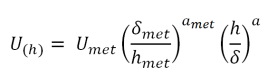
Where:
U(h) = wind speed (m/s) at height h (m)
Umet = wind speed (m/s) measured at 10m above ground level
δmet = meteorological site air layer thickness (270m– ‘Country’ exposure)
amet = exponent for meteorological site (0.14 – ‘Country’ exposure)
hmet = measurement height for meteorological (10m)
h = height above ground level (m)
| Exposure | a | δ (m) |
| Country | 0.14 | 270 |
| Urban | 0.22 | 370 |
| City | 0.33 | 460 |
Air layer thickness and exponent values for various exposures
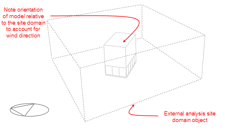
The length, width and height site domain factors are multipliers that are applied to the overall dimensions of the building model in order to arrive at an external volume or domain across which the analysis is carried out. The default factors are 3.0 applied to the length and width and a factor of 2.0 that is applied to the model height.
After clicking on the OK button, the CFD screen is displayed showing the model in conjunction with the site domain object: